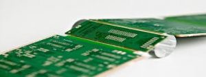
Flexible PCB Flex Circuits Can Be Integrated With Other Components
When a PCB design calls for a flexible circuit, the designer must consider the fabrication process and the materials used. These considerations will ultimately affect the final cost of the flex circuits. For this reason, it is important to have a good relationship with a preferred fabricator and communicate early and often about your designs that require flex.
The first thing to think about is the level of flexibility required by a pcb flex. For example, is the circuit going to need to be able to fold around a corner or move along a curve? If so, this will increase the manufacturing cost of the flex circuit. However, if the circuit is only going to be folded in one spot – like for a handheld ultrasound device – the cost will likely be lower.
Depending on the flex application, you may also need to select the type of flex substrate material. For instance, if you require your flex to be able to withstand the same environmental factors as rigid PCBs (heat, moisture, chemicals and shock and vibration), then selecting the correct flex material is very important.

How Flexible PCB Flex Circuits Can Be Integrated With Other Components
For instance, a flexible circuit that will be subjected to repeated creasing or movement should use a higher grade of copper than what you might find on a standard PCB. This is called Rolled Annealed copper (RA) and it is much more work-hardened than un-annealed copper. This makes it more resistant to fatigue cracking when flexed or creased repeatedly, and allows it to return to its original shape faster than un-annealed copper after the same stress.
Another consideration is the type of coverlay that will be used on the flex circuit. This is also something that should be discussed with your fab shop and fabricator. There are many different coverlay options available ranging from film-based polyimide to flexible liquid photo imageable (PI). Depending on your specific requirements you will need to determine which is best for your design and how it will be assembled.
When designing a flex circuit, you will also need to specify what components are going to be attached to it. For example, if you need to have a solder connection on your flex circuit you will need to select the proper footprints and be sure to add the appropriate traces and nets. For instance, a 0603 footprint will need a hole for the pin and a pad for the solder.
If you will have a stiffener on your flex, this should be specified early in the design phase as well. Stiffeners are strips of rigid material (can be FR4) that are added to specified areas of the flex circuit and can help to reduce the risk of signal loss during bending and movement.
Lastly, the flex layout should be designed with a view to how it will be positioned and terminated on your product. For example, if you have a slit or slot in your flex circuit it is important that the design includes a relief hole at each end of the slit or slot. This is to help prevent the slit or slot from tearing or pulling away from the flex circuit during assembly and operation of your finished product.